Back to overview
The
network
of
Evil.
USB SIM
Project by TudbuT
SIM Card to USB Ethernet adapter
A small adapter to be plugged into any PC or laptop that gives you mobile internet.
This does need a SIM card of course, which you will have to insert into it.
The total cost is about 15€.
You can buy one from me (-> contact us) for 14-17€ depending on if I can do a bulk
order at the moment, or build it yourself.
Contact us
Caveats
- LTE/4G Only!
- In the US, some of the bands aren't supported. Reception might be poor in some regions.
-
Building it yourself requires
- a bit of configuration of the LTE module, you'll need a serial terminal program.
- fine-ish soldering for the USB cable.
How to make it
Materials
- A7670C LTE Module with surrounding board (I use a FS-MCore-A7670C) - 13€
- Male USB cable with data wires - 1.5€
- Heatsink (ideally 25x25mm) - 0.5€
- Hot glue for stability on the cable
- Optional: 3D filament
Note that these are cheaper in bulk, so that about 12€ total is reachable.
Hardware setup
Soldering the USB port on (FS-MCore-A7670C)
(When referring to the "top" of the module, here I mean the side with the sim card
slot, opposite to the side with the TX/RX/etc pins. This is also how the text is
oriented.)
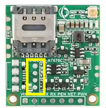
Almost directly above the serial pins are the USB pads. These are in a very
obscure order, from top to bottom: GND, D-, D+, "VBUS". This is completely non-
standard, but meh. You can check by beeping it out with the microusb pads to the
left of them. However, "VBUS" actually isnt connected to VIN, it only serves as
a USB_Enable signal. Your USB's actual VBUS should be connected BOTH to said
USB_Enable AND to the VIN pin at the bottom. You can do this by bridging two pads
as seen here (either bridge works).
This requires quite fine soldering. The module is only about 25x25mm big. Make
extra sure you don't solder to any other parts of it.
Heat sink & Hot glue
Now apply the heatsink to the shield on the other side of the module. These things
can get quite warm and would otherwise melt the hot glue we're about to apply.
The reason we even need it is that these soldering junctions are TINY, and some
strain relief is needed. Ideally don't glue directly on the junctions tho, just
in case. The heat sink and gap between it and the PCB are pretty good to apply it.
Software setup
- Ensure you have some kind of serial terminal installed
- Use settings 115200-baud, CRLF line endings(, 8N1 parity)
-
Connect the module and start the serial console. The module has two to
three ports, so you'll have to find the correct one. This is no problem tho,
just repeat until it works.
- Type `AT` into the console (and press enter). It might not display
the command back to you, but it should throw you an `OK`.
-
Set APN and enable internet:
AT+CGDCONT=1,"IP","internet"
AT+NETOPEN
-
Now you can enable the ethernet adapter mode. Run the following:
AT+DIALMODE=0
AT$MYCONFIG="usbnetmode",0
-
The device should now restart and you should get a working ethernet adapter
as a result.
3D printed case
(TBA)